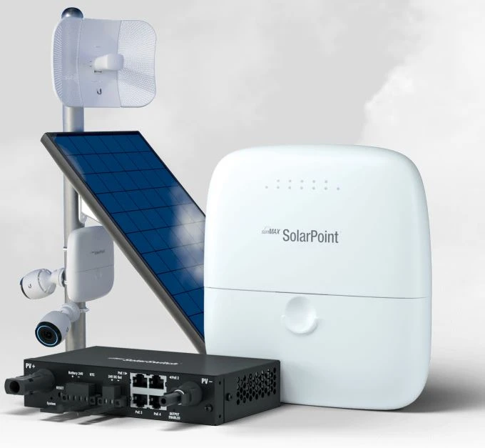
Ubiquiti SM-SP-40 | Switch | SUNMAX SolarPoint, 4x 24V PoE 100Mb/s, DC Output 40W
CODE: SM-SP-40 / EAN: 0817882028301
![Ubiquiti SM-SP-40 | Switch | SUNMAX SolarPoint, 4x 24V PoE 100Mb/s, DC Output 40W Ilość portów LAN4x [10/100M (RJ45)]](https://www.batna24.com/img2/500/327970_174633.webp?20989284258)
![Ubiquiti SM-SP-40 | Switch | SUNMAX SolarPoint, 4x 24V PoE 100Mb/s, DC Output 40W Ilość portów PoE4x [Passive PoE 24V (100M)]](https://www.batna24.com/img2/500/327970_174634.webp?20989284258)


Ubiquiti SM-SP-40 | Switch | SUNMAX SolarPoint, 4x 24V PoE 100Mb/s, DC Output 40W
CODE: SM-SP-40 / EAN: 0817882028301
79,88 GBP
without VAT (net)
Out of stock
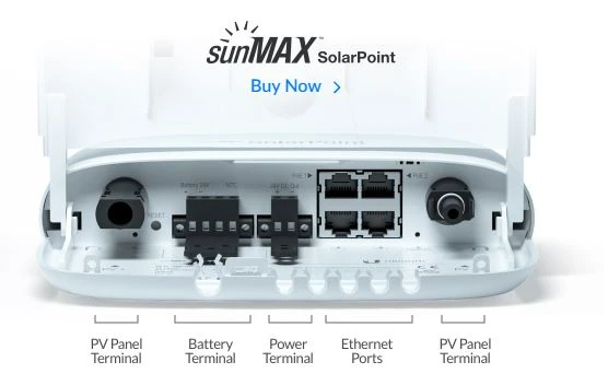
LAN standard: Fast Ethernet 10/100Mb/s
Number of LAN ports: 4x 10/100BaseTX (RJ45)
Number of PoE ports: 4x [Passive PoE 24V (100M)]
Number of WAN ports: Not applicable